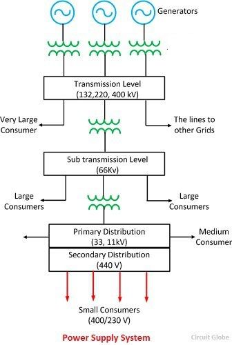
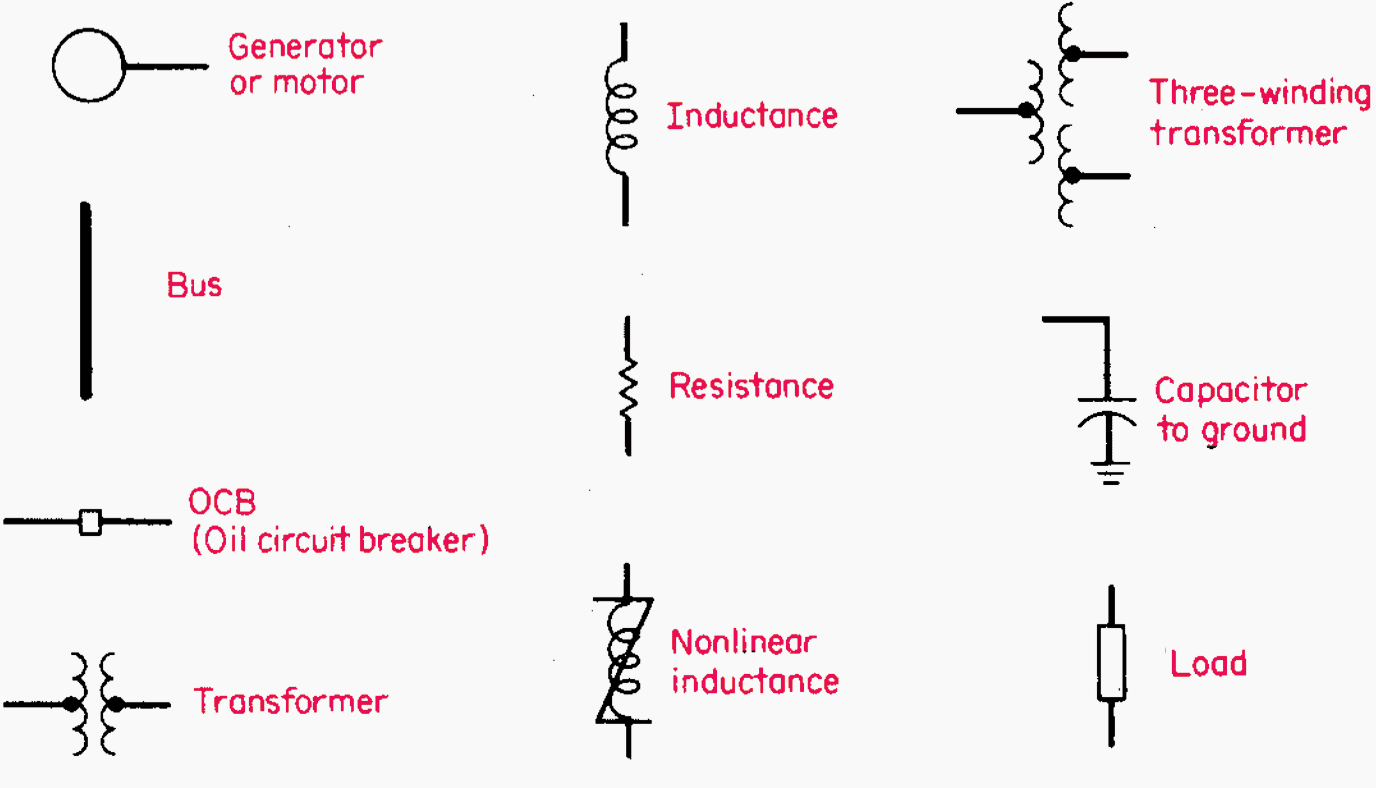
Line diagram: a one-line diagram or single-line diagram is a simplified notation for representing an electrical system. The one-line diagram is similar to a block diagram except that electrical elements such as switches, circuit breakers, transformers, and capacitors are shown by standardized schematic symbols. Figure 3—One-line diagram.
- Electrical Single Line Diagram Symbols Pdf
- Single Line Diagram Nptel Pdf
- Single Line Diagram Tutorial Pdf
- Single Line Diagram: Net Metering Fill out this document and upload to PowerClerk in the “Required Documentation” section. Non‐Utility Meter Socket Co‐Gen Meter Utility Socket (See Note #1) Check Box if Applicable Blade AC Disconnect Lockable Switch House Meter Socket Main Service Panel or Sub Panel.
- Wiring Diagram Book A1 15 B1 B2 16 18 B3 A2 B1 B3 15 Supply voltage 16 18 L M H 2 Levels B2 L1 F U 1 460 V F U 2 L2 L3 GND H1 H3 H2 H4 F U 3 X1A F U 4 F U 5 X2A R Power On Optional X1 X2115 V 230 V H1 H3 H2 H4 Optional Connection Electrostatically Shielded Transformer F U 6 OFF ON M L1 L2 1 2. IEC D-Line Control Relays 31 Class 8501 32 Type.
- ELECTRICAL AND ELECTRONICS DIAGRAMS USAS Y14.15 -1966 USA STANDARD APPROVED includes the following: 15-1 Scope 15-2 Definitions 15-3 General Infonnation 15-4 Single-Line Diagrams, General 15-5 Single-Line Diagrams (Electronics and Communications) 15-6 Single-Line Diagrams (Power Switchgear and Industrial Control).
In power engineering, a one-line diagram or single-line diagram (SLD) is a simplified notation for representing a three-phase power system.[1] The one-line diagram has its largest application in power flow studies. Electrical elements such as circuit breakers, transformers, capacitors, bus bars, and conductors are shown by standardized schematic symbols.[1] Instead of representing each of three phases with a separate line or terminal, only one conductor is represented. It is a form of block diagram graphically depicting the paths for power flow between entities of the system. Elements on the diagram do not represent the physical size or location of the electrical equipment, but it is a common convention to organize the diagram with the same left-to-right, top-to-bottom sequence as the switchgear or other apparatus represented. A one-line diagram can also be used to show a high level view of conduit runs for a PLC control system.
Balanced systems[edit]
The theory of three-phase power systems tells us that as long as the loads on each of the three phases are balanced, we can consider each phase separately.[2] In power engineering, this assumption is often useful, and to consider all three phases requires more effort with very little potential advantage.[3] An important and frequent exception is an asymmetric fault on only one or two phases of the system.

A one-line diagram is usually used along with other notational simplifications, such as the per-unit system.
A secondary advantage to using a one-line diagram is that the simpler diagram leaves more space for non-electrical, such as economic, information to be included.
Unbalanced systems[edit]

When using the method of symmetrical components, separate one-line diagrams are made for each of the positive, negative and zero-sequence systems. This simplifies the analysis of unbalanced conditions of a polyphase system. Items that have different impedances for the different phase sequences are identified on the diagrams. For example, in general a generator will have different positive and negative sequence impedance, and certain transformer winding connections block zero-sequence currents. The unbalanced system can be resolved into three single line diagrams for each sequence, and interconnected to show how the unbalanced components add in each part of the system.
Electrical Single Line Diagram Symbols Pdf
See also[edit]
References[edit]
Single Line Diagram Nptel Pdf

- ^ abMcAvinew, Thomas; Mulley, Raymond (2004), Control System Documentation, ISA, p. 165, ISBN1-55617-896-4
- ^Guile, A.E.; Paterson, W. (1977), Electrical Power Systems (2nd ed.), Pergamon, p. 4, ISBN0-08-021729-X
- ^Tleis, Nasser (2008), Power System Modelling and Fault Analysis, Elsevier, p. 28, ISBN978-0-7506-8074-5